
Avionics
Batteries
Books & Videos
Charts
Composite Materials
Covering Supplies
Electrical
ELTs
Engine Parts
Flight Training
Flight Planning
Gifts
GPS
Hardware
Headsets
Instruments
Landing Gear
Metals & Plastics
Pilot Supplies
Radios
Tires & Tubes
Tools
Wood Products
Kits & Plans
FBO Supplies
Liqui Moly AERO
Catalogs

 Shipping country set to Germany
VERTICAL POWER VP-200 CLIMATE CONTROL
Avionics_Engine-Monitors_Vertical-Power_VERTICAL-POWER-VP-200-CLIMATE-CONTROL

VP-200 Climate Control System When trouble occurs, the VP-200 CCS display tells you exactly where the problem lies. By comparison, antiquated, manual air conditioning control systems simply stop working and can be difficult to troubleshoot. SYSTEM REQUIRES VP-200 OR VP-200 DUO Features Specifications
The VP-200 Climate Control System (CCS) gives you the ability to “set and forget” the temperature in your cabin. It works with the VP-200 system, providing an integrated display for control, system monitoring, and alerting functions. Dual cabin temperature sensors are used to regulate the cabin temperature.
A color graphic display shows the status of the overall system as well as the individual fans and sensors. You can see how much current each fan is drawing, and when a fault occurs you have a clear picture of exactly where the fault lies. Dedicated switches, which you can mount anywhere in the cabin allow you to select the desired cabin temperature and manual or automatic fan operation.
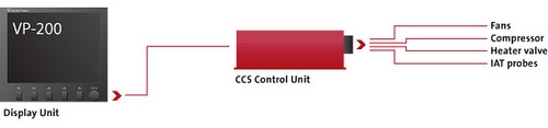
The CCS controls the air conditioning fans and compressor as well as the servos which open and close the hot air valves. A small CCS Control Unit mounts in the back of the cabin and provides power control and circuit protection to the air conditioning fans and hot air servos. A serial data line connects the CCS Control Unit to the VP-200 Display Unit.
Advanced Cabin Temperature Sensing & Control
Two inside air temperature (IAT) sensors accurately measure the cabin temperature. The CCS then controls the fans and heater valves to regulate the temperature to your desired setting.
Unlike older analog systems, the CCS controlsboth hot and cold air systems and 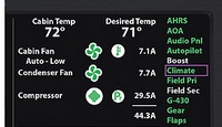 allows you to vary the system’s sensitivity to match your needs. If you want automatic air conditioning and manual heater valves, you can connect manual control cables to the heater valves and simply disable that function in the setup menus.
One or two heater valves can be controlled.Note: heating functionality not available in software until late 2008/early 2009.
Integration with the VP-200
The VP-200 system and the CCS are designed to work closely together, and many functions on the CCS are controlled in the same manner you control any other electrical device.
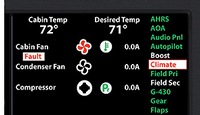
(Image of AC screen with a fault displayed, right)
The display shows the 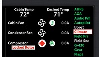 operational status of each fan, pressure switch, andtemperature switch in the system. You can graphically see the position of the heater valves. If you’re using an electric compressor from Flightline AC, it even has a computer link and the system will display those fault codes in plain language.
When a fault occurs, you can see clearly where the fault lies.
(Image of fault on screen, showing a locked rotor problem, right).
For each fan, the CCSmonitors for over-current, short circuit, or no-current-drawfaults. It also senses for IAT sensor faults, internal faults, and communication failures (with the VP-200 Display Unit). When a fault occurs, you get both visual and aural alarms.
Cabin Pressure Alarm
The CCS Control Unit also includes a cabin pressure sensor which reports cabin pressure to the VP-200 Display Unit. You can select a cabin pressure alarm limit, and when the cabin altitude limit is exceeded you receive both visual and aural alarms. The cabin altitude is also displayed on the Display Unit.
Compatibility
 Developed in conjunction with Flightline AC, the VP-200 CCS can be used with either the engine driven compressor (14v or 28v clutch) or the electrically-driven compressor (28v only).
 | = Available today |
 | = Available in 3-10 days |
 | = Available in 11 days |
") | = Unknown (3 weeks or more) |


 | Call us at +49 7634 9057700 from 08:00 to 13:00 CET |


