
Avionics
Batteries
Books & Videos
Charts
Composite Materials
Covering Supplies
Electrical
ELTs
Engine Parts
Flight Training
Flight Planning
Gifts
GPS
Hardware
Headsets
Instruments
Landing Gear
Metals & Plastics
Pilot Supplies
Radios
Tires & Tubes
Tools
Wood Products
Kits & Plans
FBO Supplies
Liqui Moly AERO
Catalogs

 Shipping country set to Germany
VERTICAL POWER VP-200 AND VP-200 DUO
Avionics_Engine-Monitors_Vertical-Power_VERTICAL-POWER-VP-200--AND-VP-200-DUO

Specifications
The VP-200 brings modern technology to the experimental aviation community to reduce wiring complexity, reduce pilot workload, and increase pilot awareness and safety. It is built using the latest technology, yet is based on time-honored electrical architectures. The system provides device switching and circuit protection, overall electrical systems management, engine monitoring, and advanced checklist functionality.
The VP-200 Series of products includes the VP-200 and the VP-200 Duo. Both are based on the same technology platform, and offer different levels of redundancy. The VP-200 Duo includes a second Control Unit which allows additional switching and control capability. It additionally supports a dual independent bus, dual alternator electrical configuration.
Modes
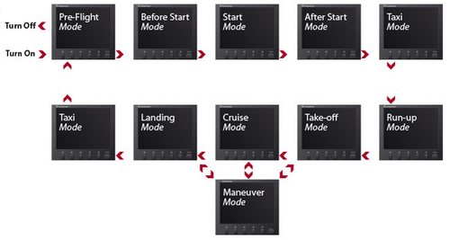
The VP-200 Series products operate around the idea of Modes.
A Mode is a specific phase of ground or flight operations. It provides a method by which to organize and clarify all of the various activities that must occur during normal operations. Using proprietary algorithms, the VP-200 takes inputs from aircraft engine data and GPS data and determines which one of ten Modes the aircraft is in. These Modes are defined as Pre-flight, Before-Start, Start, After-Start, Taxi, Run-up, Takeoff/Climb, Cruise, Landing, and Maneuver.
While this may seem like a new concept, you do it every time you fly.
As a safe pilot, you are trained to do the same things every time you fly. By its very nature, flying lends itself to automating routine tasks that are done over and over every flight. Much of your routine workload is offloaded to the VP-200 allowing you to focus on flying the aircraft. Also, pilots are usually control freaks. With that in mind, the VP-200 allows you to override automatic settings when necessary (for example, manually turning on the landing light or turning off the strobes). It also tells you exactly what it is doing and provides a real-time status display of all your electrical devices.
For each Mode, the user can:
Define what devices (lights, radios, etc.) are turned on and
off for each Mode.
Organize the display of engine instruments to optimize/de-clutter for that Mode (you may want to see different things during start than during cruise).
Configure what checklists to show at each Mode change (checklist items are user configurable).
Everything on traditionally-wired aircraft must be turned on or off manually, including lights, pitot heat, lighting, landing lights, fuel pumps, etc. You may use checklists to ensure you do not forget anything. Contrast this with recent advances in automobile technology where one finds automatic lights, windshield wipers, climate control, systems monitoring, integrated console functions, and so on. Often, when your workload is heavy or when you are distracted, items on the checklist are missed. Further, the very act of going through the checklist distracts you from the task of flying the plane itself, talking to air traffic controllers, and looking out for other traffic.
This new level of control allows you to focus on flying the aircraft (rather than managing the aircraft) and keeping your head outside the cockpit. You have total control of how the system functions. System behavior is set while you are comfortably on the ground, and rationally thinking through how things should work. Those behaviors are then executed for you while you are flying and focusing on other things.
Context
Modes give the VP-200 Series a sense of context that allows the system to accurately understand what you want to do and see from the time you power up to the time you shut down. Many instruments today display the same data throughout the flight but in practical terms, certain data are valuable at one point in time, but less valuable at another.
The idea of “context” has become popular in recent years in the software industry. For example, a software product such as a word processor may have 100 icons on the toolbar. But you only need 12 of them when editing a picture. So when you select a picture you only see the 12 you need. The others are hidden.
We’ve applied the same idea to the display and to some functions, and they’re mostly configurable by you. Here are a list of some things the VP-200 does better by understanding context:
Gauge display
You can configure which primary gauges are displayed for each mode. For example, during engine start your primary engine gauges can be oil pressure and RPM. During cruise they can be manifold pressure and RPM.
Remote Control
The remote only works when the system is in Pre-flight Mode so that you can’t accidentally use it in flight.
Master switch
The master switch is located on the Switch Panel, and will automatically turn off the electrical system when it remains in Pre-flight Mode for more than 5 minutes. No more worry about leaving the master switch on!
Flaps and trim reset
After you start the engine, the VP-200 will bring up the flaps and reset the trim to neutral. When you shut down, the flaps are lowered (for the RV folks) and the trim is reset to neutral.
Indicator bugs
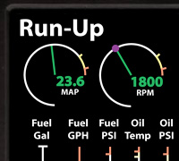
During start, you see an idle RPM bug, during run-up you see a run-up RPM bug, during cruise you see a cruise RPM bug. No reason to clutter the display with bugs you don’t need.
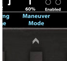
Soft Keys
The soft keys at the bottom of the display change for each mode and anticipate the actions you may want to do during that Mode as shown in the two images below.
Low voltage alarms
Normally, the low voltage light flashes when the engine is off. But it really makes no sense because we all know the voltage is low. The VP-200 allows you to specify a low voltage threshold for both engine off and engine on conditions.
VMC-IMC conditions
You can configure one of the three switch panel switches to be a VMC-IMC switch. If you’re in VMC conditions, place the switch in VMC. Before you go in the clouds, place it in IMC position. When in IMC, it will turn off the strobes, turn on pitot heat below 40 deg F, and respond more quickly to certain emergencies. Specifically, you can configure different load-shedding scenarios for IMC and VMC conditions so that if you do have an alternator failure, you shed only those devices appropriate to the weather conditions.
De-clutter
The flap and gear indicators disappear in Cruise Mode if they are UP. EGTs are not shown when the engine is off. The Takeoff Mode checklist disappears when the airplane is faster than 20 kts. To name only a few.
Start code—no key needed

During Before Start Mode, the system asks you to enter a code before allowing you to engage the starter.
Intelligent contactor control
The system automatically determines when to turn on and off the battery contactor, and does not engage the battery contactor until it is needed. This draws less power on the ground during pre-flight and emergency load shed conditions.
Runaway trim protection
There are two runaway trim protection systems, and one works differently on the ground than in the air. If the trim runs for more than three seconds in the air, the circuit is disabled. However, you can run it indefinitely when on the ground.
Mag switch position checking
During engine start, takeoff, and after engine shutdown the VP-200 checks that the mag switch is in the right position, and warns you if it is not.
Variable trim speed

The pitch trim motor speed adjusts automatically so it becomes less sensitive in cruise and more sensitive in the pattern.
Air or ground context

The system determines (and displays) if you are in the air or on the ground. With that information, it can assume certain things. For example, the landing gear circuit is disabled on the ground, so you don’t have to wire in a separate system to provide this function.
Maneuver Mode
The system determines (and displays) if you are in the air or on the ground. With that information, it can assume certain things. For example, the landing gear circuit is disabled on the ground, so you don’t have to wire in a separate system to provide this function.
Wiring With Vertical Power
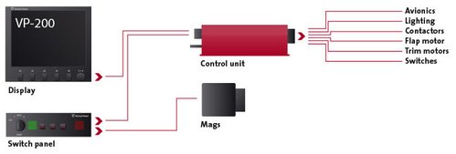
Wiring your airplane is a serious project. No one can make it easy, but we can make it a lot easier. We provide complete instructions, how-to guides, tool rentals, wiring harnesses and wiring diagrams to assist with your project
Rather than point to point to point wiring, you wire from the Vertical Power Control Unit (CU) to the electrical devices. Run a wire from the CU to the landing light. Run a wire to the starter contactor. Run a wire to the transponder. Run a bundle of five wires to a trim servo. Run two wires to the flap motor. Run a wire from each trim switch to the CU. Until you’re done. You get the idea.
Then use the setup menus on the Display Unit to configure your system. You tell it what devices you have, what the circuit breaker values are, and when each device should turn on or off. You configure the engine parameters, external switch inputs, and various behaviors (like whether or not to raise the flaps after engine start).
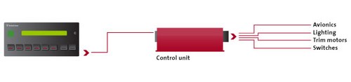
Wiring the VP-100/VP-50:
Safety Features
Graphical electrical display: view the entire electrical system in graphical format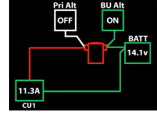 and when a problem occurs you can see exactly what it is.
Runaway trim protection: If your trim switch sticks or one of the switch wires shorts, you can stop the trim from running by pressing the opposite trim button. Soon the trim switches are automatically disabled and you can use the backup trim switches.
Automatic boost pump activation: If the fuel pressure drops, the boost pump can come on automatically.
Backup circuits: you can easily wire backup circuits for critical instruments, providing an additional layer of safety.
Wig-wag the landing lights: this provides additional visibility in the air, and the lights can automatically go steady below a certain airspeed providing additional safety near the ground.
Quick response to emergencies: press the red emergency button, then another button to specify the emergency and the emergency checklist appears and a pre-configured set of actions occurs to resolve the emergency.
Current fault alerts: know right when a landing light burns out, not at your next pre-flight.
Aircraft configuration checks: ensure that electrical devices, mag switch, landing gear, and trim & flap control surfaces are configured correctly for engine start, takeoff, and landing.
Load shedding: you can load shed different electrical devices for VMC or IMC conditions, leaving on those best suited for the particular weather conditions at the time.
Audio alerts for electrical failures: an alarm in your headset, as well as a visual display, alerts you when an electrical failure occurs so you know exactly when it happens. With fuses or breakers, you may not notice the failure until you actually need the failed device.
Dual solid-state switches on critical circuits: additional safety is built into critical functions like the trim, flaps, and starter circuits to mitigate the risk of hardware failures causing inadvertent activation.
The Vertical Power Advantage
Here are some reasons to consider a modern, solid-state electrical system for your experimental aircraft:
Handles routine tasks.
The VP-200 handles routine tasks for you so you can focus on flying the airplane and keeping your head outside the cockpit. It can turn on your boost pump and landing lights at takeoff or landing, turn on your alternator and avionics automatically after engine start, inflate and deflate the canopy/door seal, and set your trim and flaps while on the ground, to name just a few.
Advanced features.
Without complex wiring or additional modules, you can incorporate advanced features into your aircraft like reduced trim sensitivity at speed, auto trim compensation when lowering flaps, intermediate flap settings, wig-wagging the landing lights, automatic switching to the backup alternator, configurable load-shedding, disabled landing gear on the ground, and alerts when the landing & taxi lights fail.
Rapid emergency detection and response.
You are notified of engine and electrical faults with voice and visual alarms. And when you need to respond to an emergency, you can see an emergency checklist and activate a pre-configured set of actions with two simple button presses.
Safety features.
The VP-200 also includes important safety features like runaway trim protection and reminders when the mag switch is set in the wrong position. A graphical electrical system display shows you the status of the electrical system in clear, concise graphics and is updated in real time. When a failure occurs, you know exactly what’s happening.
Makes changes easier.
Thinking about adding a backup alternator or installing a new electrical device in the future? Need to change a circuit breaker value? Want to change what is on your emergency bus? With little or no wiring you can make these changes using the on-screen setup menus.
Clean, simple panel.
For those who value a clean, clutter-free instrument panel, the Vertical Power system goes a long way towards helping you achieve this goal. Many switches, annunciators, and lights are built into the Vertical Power products.
Reduces parts count and complexity.
You don’t have to buy fuse blocks, diodes, circuit breakers, most switches, over-voltage & under-voltage modules, trim modules, voltage converters, relay decks, indicators, annunciator lights, mechanical engine gauges, key switches, flap controllers, dimmers, or landing gear disable systems. No more complex wiring diagrams. Fewer connections and mechanical components means fewer opportunities for failure.
Reduces build time.
Not having to plan, draw wiring diagrams, and actually wire all the components in the previous paragraph saves a lot of time. Wiring is simplified because you run power wires from the Vertical Power system directly to the electrical devices that need power such as the avionics, flaps, trim motors & switches, and contactors.
Convenience features.
Enjoy the convenience of automatic shut-off of your electrical system if left on after flight - never leave the master switch on again! Plus, convenience features like voice alerts and a remote key fob that you can use to turn on the cabin lights or unlock the canopy.
 | = Available in 2 days |
 | = Available in 3-10 days |
 | = Available in 11 days |
") | = Unknown (3 weeks or more) |
| 11-06380 | VERTICAL POWER VP-200 HARNESS | 616.80 EUR | |


 | Call us at +49 7634 9057700 from 08:00 to 13:00 CET |


