
Search
Categories
Airframe Parts
Avionics
Batteries
Books & Videos
Charts
Composite Materials
Covering Supplies
Electrical
ELTs
Engine Parts
Flight Training
Flight Planning
Gifts
GPS
Hardware
Headsets
Instruments
Landing Gear
Metals & Plastics
Pilot Supplies
Radios
Tires & Tubes
Tools
Wood Products
Kits & Plans
FBO Supplies
Liqui Moly AERO
Catalogs

Katalog nur für gewerbliche Kunden. Alle Preise zzgl. MwSt.[Preise inklusive MwSt zeigen]
 Shipping country set to Germany
Ae Airspeed Switch + Board
| Part number: | 10-01817 |
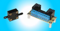

Description:
When our relay board is used with our airspeed switch, you can protect you flaps from being actuated in the downward direction when your airspeed is too high (above the white arc). We provide the end user with easy connection diagrams for several different systems.
Automatic Elevator Trim Motor Speed Adjust at different airspeeds
Many have complained about the fast adjustment speed of elevator trim motors at high airspeeds. When our relay board is used with our airspeed switch, it eliminates this problem. You will have two speeds, fast for slower airspeeds, and slower for high airspeeds. The slower speed is adjusted by supplying this relay board a lower motor drive voltage.
DETAILS for the Automatic Elevator Trim Motor Speed Adjust
- Connect the airspeed switch to your aircraft pitot tube and static air.
- Connect the airspeed switch output, to drive the relays on the relay board. See the appropriate diagram below.
NOTE: The airspeed sensor will only drive light loads such as the relay board coils. - Use the output of the relay board to switch from one of two voltages that will be used to drive your elevator trim motors.
- The one item you will have to supply, is the alternate lower voltage source for your slower speed. You may use simple diodes or zener diodes in series with your 12Vdc supply, or use an adjustable source like the "Ray Allen Company's" Speed Control. Click the link below to view and/or print out a suggested connection diagram.
- Connect the airspeed switch to your aircraft pitot tube and static air.
- Connect the airspeed switch output, to drive the relays on the relay board. See the appropriate diagram below.
NOTE: The airspeed sensor will only drive light loads such as the relay board coils. - Use the output of the relay board to activate or disable your flap down electronics. See the appropriate diagram below.
Airspeed Switch
- Pull-in airspeed adjustable with a screw driver
- Switch Current Rating: 0.04A max.
- Adjustable from 70 MPH to 160MPH
Relay Board
- Mounting Hardware included
- Relay contacts protected against arcing from inductive loads such as motors.
- Switch contacts
- Two relays, SPDT (Single Pole, Double Throw)
- 10A max. current
- Relays are 12V relays
| Unit | EA |
| Hazardous | No |
| Oversize | No |
| Weight | 0.136 kg |
| Manufacturer | |
| Manufacturer P/N | |
| GTIN | |
| Core Charge | Yes (add to cart to see price) |
| 110V device | Yes |
This part is included in the following categories:

Log in
Shopping cart is empty
Subtotal incl. VAT:0 EUR
Latest News


 | Call us at +49 7634 9057700 from 08:00 to 13:00 CET |


